As you may have read in our recent blog post, engineers and GIS professionals don’t do the same type of work, and so they use different software solutions that rely on different functionalities and produce their output in different formats. Luckily, FME’s ETL (extract, transform, load) tools make it possible to retrieve information from an engineer’s CAD drawings and integrate it into a GIS, and the other way around. When going from CAD to GIS, these are the three basic steps to follow:
1. Choose a Reader
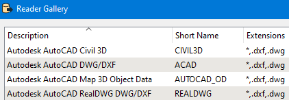
Search for DWG as a format on FME’s readers list and you’ll find quite a few options. All of the readers below can be used to read CAD data in DWG or DXF format, but each serves a different purpose and uses different parameters.
In addition to using Safe Software’s detailed guide to choosing a format, we draw on the many projects we’ve successfully delivered for our clients to help you sort your options out. Here at Consortech, we’ve gone around the CAD-to-GIS block more than a few times!
AutoCAD Civil 3D
This format is primarily intended for use with the AutoCAD product Civil 3D. You can use this reader if the drawings were created in Civil 3D for a sewer or water system, even if they’ve been modified in AutoCAD later. It bears mentioning that if you use other AutoCAD readers for files in Civil 3D format, some application-specific geometries may not be supported.
AutoCAD DWG/DXF
This is the most common and most basic of the readers. It supports standard AutoCAD entities and uses libraries from the Open Design Alliance to read and write DWG files.
AutoCAD Map 3D Object Data
This reader can manage object data information that is available in AutoCAD Map 3D. In order to be able to read and write object data, you have to use a drawing that has been designed with or is meant to be used in AutoCAD Map 3D.
AutoCAD RealDWG DWG/DXF
This reader uses Autodesk’s Trusted DWG library, which lets you choose the AutoCAD version (by year) that will be used to both read and write your DWG files. While this format is better than the more basic DWG/DWX Reader at supporting 3D geometry such as surfaces and solids, it does require more machine power and is only supported on Windows 64-bit and on FME 2020 or higher.
2. Extract the data you need
Although AutoCAD drawings do not handle attributes in the same way a GIS does, they do contain quite a bit of useful information that you can extract into the GIS.
Geometries
Each geometry will be read in FME as its own feature, so you can treat every line, point and polygon however you like. Take blocks, for instance, a common AutoCAD geometry in the context of land management. A block is a collection of lines, points and polygons that are combined into a single object with an insertion point. While a GIS professional would apply a style to a layer of points representing a fire hydrant, an engineer might add a fire hydrant block in AutoCAD to make a drawing more visually representative.
When managing blocks in AutoCAD, you have two options:
- Preserve only the insertion point
- Preserve the geometries that make up the block
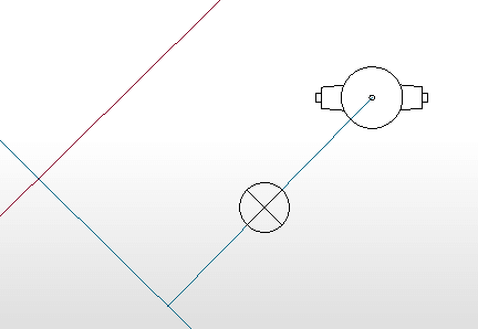
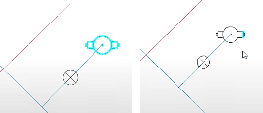
Since blocks are made up of lines, polygons and points, they can be exploded with FME. Exploding a block means breaking it down into its component parts. Once exploded, the fire hydrant block above will no longer be a combined element (left), but rather a set of circles, rectangles, and individual lines (right).
The parameter to explode your blocks is in the Reader options.

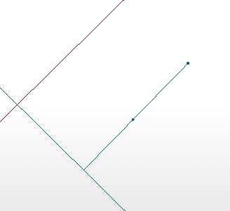
Beware, however, that if you uncheck this option, your blocks will not be imported as an entity like in the image further up. Instead, an insertion point will appear where the block normally would.
Style (colour, line, width, etc.)
Another way to get information is to use AutoCAD entity styles such as colour, line width and line type. In some cases, a specific style can be applied to an entire entity category (e.g., size 3 blue line to represent a water pipeline); the process of transferring these entities to the right layers in your GIS can then be automated.
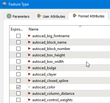
All style information is entered using the Format Attributes under the Feature Type parameters. Just expose them by checking the box and they’ll be displayed in your FME Workspace. They can also be used by subsequent transformers.
Object data attributes (if available)
If a CAD drawing has been produced in AutoCAD Map 3D, there may be Object Data attached to the features. This data will appear as attributes directly in the FME workbench. For more information on working with this reader parameter, check out this article by Safe Software.
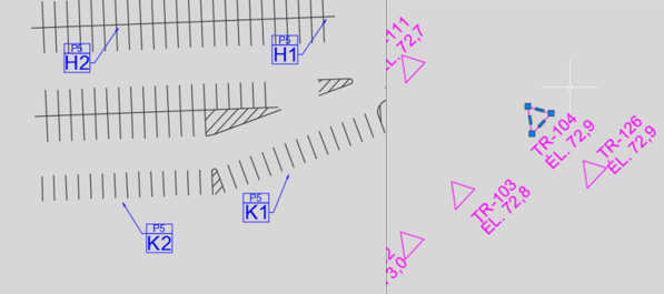
Text and Labels
Because standard AutoCAD entities don’t usually have attributes (unless they have object data), the information regarding a feature usually appears as a note or text nearby. You can use FME’s spatial join transformers, such as NeighborFinder and SpatialRelator, to retrieve information from neighbouring notes and attach them to CAD entities.
3. Transfer the information to your GIS
Once the CAD data has been read and correctly interpreted within FME, it’s time to transfer it to your GIS. This can be done in two steps:
a. Match the extracted information with the attributes in your GIS
Once the information in the object data or in the notes has been extracted from the CAD file within FME, all you have to do is assign it to the existing attributes in your GIS. You’re probably going to want to use the AttributeManager and AttributeCreator transformers for this operation.
b. Validate the geometries
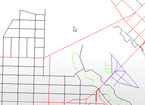
We cannot stress this step enough: you need to check your geometries! With all the freedom you get creating your drawings in AutoCAD, there’s a good chance you’ll end up with multiple kinds of geometry on the same layer, which is a problem for GIS that is more strictly structured. And that’s not even mentioning that in many cases, the topology will need to be corrected. This can lead to problems when the time comes to conduct geomatics analysis. It can also result in polygons that are not closed or snapped correctly.
Transformers such as GeometryFilter and GeometryValidator can be used to make sure the geometries are correct and not corrupted so they can be transferred to the GIS. If using GeometryFilter or GeometryValidator causes any data to be lost, the simplest way to fix it is to do it manually, either in the original drawing or, post-transfer, directly in the GIS. This is yet another case in which the Pareto principle applies: sometimes, a few manual steps can spare you from having to build overly complex processes to try to account for every single possibility.
Next up: Producing CAD data from your GIS
We’ve shown you how FME can help you apply the ETL method to your CAD data, and how you can read it more efficiently (extract), retrieve information from it (transform) and integrate it to a GIS (load).
This sequence may be automated to varying degrees, but good old Pareto is here to remind us that it is possible to maximize your productivity gains all while keeping your effort and investment to a minimum!
Once you’ve accomplished this project, we think you’ll be chomping at the bit to try it the other way around: how about producing CAD data from your GIS next?
Are you looking for ways to make importing CAD data into your GIS more efficient?